Figure - 1
2 Mar 2013
kenglong@gmail.com
<-- Back to main subnetting page
While it's nice to be able to go through a procedure to calculate all the different numbers in a subnetting problem, it doesn't really help us to know why we need to do subnetting. There are several reasons why we need to subnet. One is to keep our networks to a manageable size to improve performance, manageability and security. Another reason is to preserve a limited supply of IP addresses. Is there a limit to how small we want our networks? Yes. Every time we subnet and create another network, we need a router or layer 3 switch to connect it to the other networks. So, one of the limiting factors is hardware cost. With that in mind, lets see if we can apply what we've learned about subnetting to a more practical problem.
We have been given a class C IP address,
192 . 168 . 10 . 0.
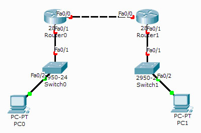
We have two groups of devices separated by two routers. (See Figure 1.) We need to subnet our new class C to provide three subnetworks. The first will be used for the PC0 group which has 8 devices, the second will be used for the PC1 group which has 9 devices but there is an expansion project being planned which will add another 4 devices, and the third network will be used to connect the two routers together.
Figure - 1
Create an efficient subnetworking plan which will provide the required networks and accomodate the required number of devices in each network.
The general procedure is
Since we're starting with a class C, the default mask is 255 . 255 . 255 . 0. We need three subnetworks. We could start by calculating the number of bits we need to borrow from the host portion to create three subnetworks. Three is not an even power of two. The next higher power of two is four or 22. That means we need to borrow two bits making a mask of /26. While that would create the required three networks, it would be wasteful because it would create three networks with 26 - 2 = 62 valid host addresses on each subnetwork. Remember, we only need a maximum of 13 valid host addresses on each subnetwork. So, in order to create an efficient subnetworking plan, we should start by calculating the number of HOST bits we need rather than the number of SUBNETWORK bits we need to borrow.
Ok, we need a maximum of 13 valid host addresses per subnetwork. Don't forget to account for the two extra addresses for the network and broadcast. That means we really need 15 total IP addresses per subnetwork. We'll use the same technique as above. First, 15 is not an even power of two. The next higher power of two is 16 or 24. That means we need 4 bits for the HOST portion. That leaves 4 bits for the subnetworking portion. That makes our new subnet mask
255 . 255 . 255 . 11110000 which converts to 255 . 255 . 255 . 240 or /28
Can you see how this is more efficient than simply borrowing 2 bits from the host portion to create a mask of /26? With a /26, we can address all of our devices and keep the three subnetworks separated but we would be using the entire class C that was assigned to us. With our efficient plan, we created 16 subnetworks and only used three leaving 13 subnetworks for future use.
We have our mask. Now we need to calculate the network numbers. Because we borrowed four bits or 24, we will be incrementing the subnetwork numbers by 16. We start at zero and count up by 16's.
192 . 168 . 10 . 0
192 . 168 . 10 . 16
192 . 168 . 10 . 32
192 . 168 . 10 . 48 We can stop here because we only need three subnetworks.
Now that we have the network numbers, we can fill in the rest to complete our plan.
192 . 168 . 10 . 0 First subnetwork number
192 . 168 . 10 . 1 First valid host
192 . 168 . 10 . 14 Last valid host
192 . 168 . 10 . 15 Broadcast
192 . 168 .10 .16 Second subnetwork number
192 . 168 . 10 . 17 First valid host
192 . 168 . 10 . 30 Last valid host
192 . 168 . 10 . 31 Broadcast
192 . 168 .10 . 32 Third subnetwork number
192 . 168 . 10 . 33 First valid host
192 . 168 . 10 . 46 Last valid host
192 . 168 .10 . 47 Broadcast
Now we can assign IP addresses, subnet masks and default gateways to all of our devices. Let's use the 10.0 subnetwork for the PC0 subnetwork, the 10.16 subnetwork for the PC1 subnetwork and the 10.32 subnetwork to interconnect the two routers.
Router 0
Fa0/1
IP: 192 . 168 . 10 . 1
SM: 255.255.255.240
Fa0/0
IP: 192 . 168 . 10 . 33
SM: 255.255.255.240Router 1
Fa0/0
IP: 192 . 168 . 10 . 34
SM: 255.255.255.240
Fa0/1
IP: 192 . 168 . 10 . 17
SM: 255.255.255.240PC0
IP: 192 . 168 . 10 . 14
SM: 255 . 255 . 255 . 240
GW: 192 . 168 . 10 . 1PC1
IP: 192 . 168 . 10 . 30
SM: 255 . 255 . 255 .240
GW: 192 . 168 . 10 . 17
With everything configured as above, we can ping from PC0 to both interfaces on Router 0 and from PC1 to both interfaces on Router 1. If we configure routes on the routers, we'll be able to ping all the way across from either PC to the other PC. Everything works and our plan is complete.
Can you see where we might be able to make our plan even more efficient? Hint: we only need two host addresses to interconnect the two routers.
So, let's make the plan even more efficient by taking one or our new subnetworks and subnetting it again to create a network with only two IP addresses. Let's use the last subnetwork, 192 . 168 . 10 . 240. Because we need only two hosts (four total IP addresses) we only need 2 HOST bits. That makes our mask:
255 . 255 . 255 . 11111100 which converts to 255 . 255 . 255 . 252 or /30
Looking at the subnetwork bits, we can see that the first one from the right is in the 4's place. That makes our increment 4. Starting at 192 . 16 . 10 . 240, we count by fours to get all of our new subnetwork numbers.
192 . 168 . 10 . 240
192 . 168 . 10 . 244
192 . 168 . 10 . 248
192 . 168 . 10 . 252
192 . 168 . 10 . 256 (this subnetwork number is not valid but it's included here to make filling in our plan easier.)
Just like we did above, we can now fill in the first host, last host and broadcast addresses to complete our plan.
192 . 168 . 10 . 240 First subnetwork number
192 . 168 . 10 . 241 First valid host
192 . 168 . 10 . 242 Last valid host
192 . 168 . 10 . 243 Broadcast
192 . 168 .10 .244 Second subnetwork number
Now we can assign the new host addresses to the Fa0/0 router interfaces with the new mask. The new router settings become:
Router 0
Fa0/1
IP: 192 . 168 . 10 . 241
SM: 255.255.255.252
Fa0/0
IP: 192 . 168 . 10 . 33
SM: 255.255.255.240Router 1
Fa0/0
IP: 192 . 168 . 10 . 242
SM: 255.255.255.252
Fa0/1
IP: 192 . 168 . 10 . 17
SM: 255.255.255.240
That completes our subnetting plan. We have fulfilled all the requirements and we have 13 subnetworks with 14 valid hosts each and three subnetworks with two valid hosts each left over for future use. (I had trouble making the Packet Tracer simulation work as shown using RIP. It works with static routes. Mr. Clauss informed me that I had to configure RIP ver 2 on each router to get support for subnetted networks. Once I did that, it worked fine. Thanks to David Clauss from CNM.)